Entity Relationship Diagram – ERD Symbols, Examples, and How to Create One | DbSchema
Table of Contents
- What an entity relationship diagram is
- Core ERD concepts
- How to read an ER diagram visually
- Cardinality in an ER diagram
- Common ERD symbols and notations
- Conceptual, logical, and physical ER diagrams
- Entity relationship diagram example
- How to create an ER diagram step by step
- ER diagram vs relational schema
- What to look for in an ERD tool
- Create ER diagrams in DbSchema
- Common ERD mistakes
- FAQ
- Conclusion
An entity relationship diagram (ER diagram or ERD) is a visual map of a database. It shows the entities you store data about, the attributes inside each entity, and the relationships that connect them.
For searchers comparing definitions, symbols, and examples, the practical value is simple: a good ERD makes a schema understandable at a glance. Instead of reading CREATE TABLE statements line by line, you can see keys, foreign keys, and many-to-many tables in one view. That is why ERDs are still essential for database design, reverse engineering, and documentation in 2026.
What an entity relationship diagram is
An ERD helps you answer questions such as:
- what tables exist in the database?
- which column is the primary key?
- how does one table link to another?
- is the relationship one-to-one, one-to-many, or many-to-many?
- are there missing constraints or duplicated structures?
That makes ER diagrams useful in two very different situations:
- design-first projects, where you sketch the model before the database exists
- documentation projects, where you reverse-engineer an existing schema and explain it to the rest of the team
If you are new to relational modeling, pair this guide with Steps to Design a Relational Schema and How to Design a Relational Database Schema.
Core ERD concepts
You do not need every notation on day one, but you should know these basics:
- Entity: usually a table such as
Customers,Orders, orBooks - Attribute: a column such as
customer_idoremail - Primary key: the column or column set that uniquely identifies a row
- Foreign key: a column that references another table's key
- Relationship: the link between two entities
If you understand tables, columns, primary keys, and foreign keys, you already understand the core of most ER diagrams.
If keys still feel fuzzy, read Primary Key in SQL, What Is a Foreign Key?, and the DbSchema page about foreign keys.
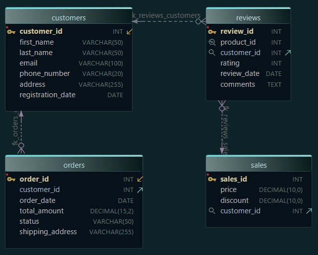
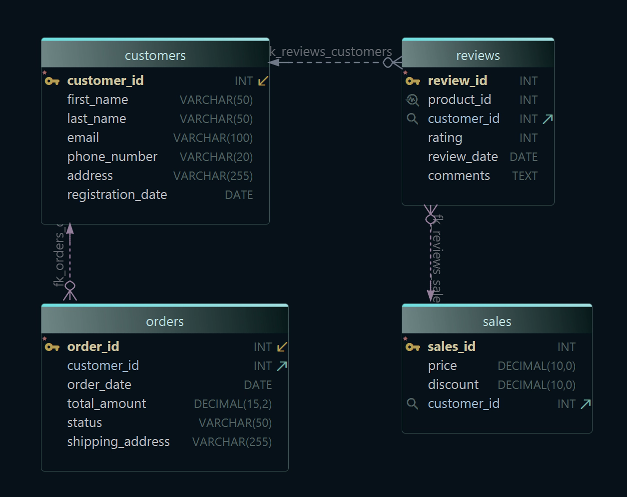
How to read an ER diagram visually
Many pages explain what an ERD is, but fewer explain how to read one fast. A practical review order looks like this:
| Visual cue | What to check first | Why it matters |
|---|---|---|
| Primary key columns | find the unique identifier in each table | tells you how rows are referenced |
| Foreign key columns | follow child-to-parent links | shows data dependencies |
| Junction tables | look for two foreign keys and little business data | usually means many-to-many |
| Crow's foot or line endings | inspect the relationship markers | reveals one-to-one vs one-to-many |
| Nullable foreign keys | ask whether the relationship is optional | affects validation and business rules |
When you review a real schema, start with the tables that anchor the business domain, such as Customers, Orders, or Invoices. Then move outward to lookup tables, link tables, and optional child tables. This is the same workflow DbSchema uses well because you can open the diagram view, click a table, and immediately follow related tables visually instead of searching through raw SQL files.
Cardinality in an ER diagram
Cardinality tells you how many rows in one entity can relate to rows in another entity.
One-to-one (1:1)
One row in table A matches one row in table B.
Example:
UsersUserProfiles
This is useful when optional or security-sensitive details should live separately.
One-to-many (1:N)
One row in the parent table can match many rows in the child table.
Example:
- one
Customer - many
Orders
This is the most common relationship pattern in relational databases.
Many-to-many (M:N)
Many rows in table A can match many rows in table B. In a relational database, you implement this through a link table.
Example:
- many
Books - many
Authors - link table
BookAuthors
Understanding cardinality is what lets you draw the lines between tables correctly instead of treating the ERD like a set of disconnected boxes.
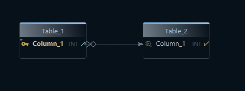
Common ERD symbols and notations
Different tools and books use slightly different notation styles. The most common ones are:
| Notation | Common use | What you will usually see |
|---|---|---|
| Crow's Foot | practical database modeling and schema tools | entities as boxes with cardinality markers |
| Chen notation | conceptual modeling and education | entities, attributes, and relationships as separate shapes |
| IDEF1X | formal enterprise data modeling | strong emphasis on keys and identifying relationships |
In day-to-day database tools, including DbSchema, you will mostly think in terms of:
- entities as boxes
- keys as marked columns
- relationships as lines
- crow's foot markers or similar line endings for cardinality
You may also hear about:
- strong entities: can exist independently
- weak entities: depend on another entity for identity
- derived attributes: values calculated from other data
- multivalued attributes: attributes that often need a separate table in relational design
For most teams, the practical goal is not memorizing every symbol. It is understanding which tables depend on which others and why.
Conceptual, logical, and physical ER diagrams
One reason competitor pages rank well is that they explain ERDs at multiple levels of detail.
| Type | Focus | Typical contents | Best use |
|---|---|---|---|
| Conceptual ERD | business overview | entities and broad relationships | stakeholder workshops |
| Logical ERD | design detail | entities, attributes, keys, normalized structure | database planning |
| Physical ERD | implementation detail | tables, column types, indexes, constraints | deployment and reverse engineering |
When to use each level
- use a conceptual ERD when you are discussing the domain with non-technical stakeholders
- use a logical ERD when you are refining the data model
- use a physical ERD when you are implementing or reverse-engineering the real schema
The logical design documentation and schema documentation guide are useful once you move beyond the conceptual stage.
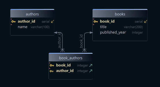
Entity relationship diagram example
Here is a small library example:
- Books →
book_id,title,published_year - Authors →
author_id,name - BookAuthors → link table between books and authors
Why use the extra table? Because one book can have multiple authors, and one author can write multiple books. That is a classic many-to-many relationship.
You can also move from SQL to a diagram directly:

That is one reason ERDs are so useful in real projects: they help both people who think visually and people who start from DDL.
How to create an ER diagram step by step
Most high-ranking guides include a clear process. A practical version looks like this:
-
Identify the entities.
Start with the main things the system stores: customers, products, invoices, employees, or tickets. -
List the attributes.
Add the columns that belong to each entity and separate core business data from lookup values. -
Choose the primary keys.
Decide how each row is identified. Surrogate keys are often simpler than overloaded business keys. -
Add foreign keys and relationships.
Connect entities based on how the data relates in the real world. -
Check cardinality.
Decide whether each relationship is 1:1, 1:N, or M:N. -
Normalize or simplify where needed.
Remove duplication, split repeating groups, and introduce junction tables when necessary. -
Review with real queries in mind.
The best ERD is not just theoretically clean; it also supports the application's access patterns. -
Document and share the design.
A diagram is most useful when the team can revisit it later.
For a broader workflow, see Steps to Design a Relational Schema. If you are working with a live schema, connect to the database, reverse-engineer the model, and refine the diagram instead of redrawing everything manually.
ER diagram vs relational schema
People often search for these terms interchangeably, but they are not the same thing.
| ER diagram | Relational schema |
|---|---|
| visual representation of entities and relationships | structural definition of tables, columns, keys, and constraints |
| useful for design reviews and documentation | useful for implementation and SQL generation |
| easier for non-technical stakeholders to understand | more precise for developers and database engines |
In practice, good teams use both. They sketch or reverse-engineer the ERD, then generate or review the relational schema. DbSchema is useful here because the same model can drive the diagram, the generated SQL, and the exported documentation.
What to look for in an ERD tool
If you are choosing a tool in 2026, these capabilities matter most:
| Capability | Why it matters | Practical DbSchema workflow |
|---|---|---|
| visual design | faster reviews and fewer modeling mistakes | draw tables and links before writing SQL |
| reverse engineering | saves time on existing databases | import a live schema through JDBC |
| documentation export | turns diagrams into reusable team assets | publish HTML docs for developers and analysts |
| schema synchronization | keeps the model aligned with production | compare the model against the live database |
| multi-diagram organization | makes large schemas readable | split one database into focused views |
If you are comparing tools directly, read Top Free Tools for Database Design, Best MySQL Database Design Tools, and Top Free ER Diagram Tools for PostgreSQL.
Create ER diagrams in DbSchema
DbSchema is built for exactly this workflow. You can use it in two common ways:
1. Draw the schema first
Create the tables, keys, and relationships visually, then let DbSchema generate the SQL.
2. Reverse-engineer an existing database
Connect through a driver such as the PostgreSQL JDBC driver or MySQL JDBC driver, import the schema, and let DbSchema build the diagram from the live database.
This gives you several advantages:
- visual editing of primary keys and foreign keys
- model-to-database synchronization
- database-to-model refresh
- schema documentation exports
- a diagram your whole team can understand
The diagram documentation, connect-to-database guide, and schema documentation guide cover the workflow in more detail. If you want database-specific walkthroughs, start with Create ER Diagrams for MySQL or Create ER Diagrams for PostgreSQL.
Common ERD mistakes
-
Skipping primary keys
Without a clear key, the relationships become ambiguous. -
Ignoring cardinality
A line between tables is not enough; you need to know whether the relationship is 1:1, 1:N, or M:N. -
Mixing conceptual and physical detail carelessly
If one part of the diagram is business-level and another part is full of storage-level details, the model gets harder to read. -
Using too many smart keys
Overloaded identifiers make the schema harder to evolve. -
Letting the diagram drift away from the real database
A stale ERD quickly loses trust. That is why synchronization features matter.
FAQ
What is the purpose of an entity relationship diagram?
An ER diagram shows tables, columns, and relationships visually so you can design, review, and document a database faster than by reading raw SQL alone.
What symbols are used in an entity relationship diagram?
That depends on the notation, but the common elements are entities, attributes, keys, and relationship lines with cardinality markers.
What is cardinality in an ER diagram?
Cardinality describes how many rows in one entity can relate to rows in another entity.
What is the difference between an ER diagram and a UML diagram?
An ER diagram focuses on data structure and relationships. UML class diagrams focus on software objects and behavior more broadly.
What is the difference between conceptual, logical, and physical ER diagrams?
Conceptual ERDs show the business view, logical ERDs show the design view, and physical ERDs show the implemented database details.
How do I create an ER diagram from an existing database?
Use a schema tool such as DbSchema to reverse-engineer the live database and generate the diagram automatically through connect to database.
What free tools can I use to create an ER diagram?
Many tools exist, but if you want both visual design and live database synchronization, DbSchema is a strong practical option because it combines ER diagrams, SQL generation, and documentation.
Can an ER diagram help with database documentation?
Yes. A maintained ERD is one of the fastest ways to onboard developers, analysts, and stakeholders. DbSchema can turn the same model into interactive schema documentation and HTML docs.
Conclusion
An entity relationship diagram helps you understand a database faster than raw DDL alone. Once you know the entities, keys, relationships, and cardinality, the schema becomes much easier to design, review, and explain.
Use DbSchema when you want to draw ERDs visually, reverse-engineer them from an existing database, and keep the model synchronized with the real schema instead of letting the documentation drift.