Logical Database Design: Keys and Normalization
For an architect settling the structure of a database before the engine is chosen; identifying relationships and the three normal forms are worked through on one example.
On this page
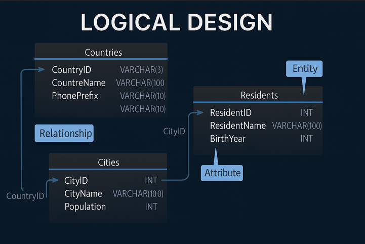
You called the meeting to agree on the entities, and forty minutes in it is about whether a column should be VARCHAR or TEXT. That question belongs to a later stage. Logical design is where you settle the structure itself, and a model at that stage names no engine anywhere in it.
Get the structure right and the physical schema is a translation of it. Get it wrong and no index repairs the result, because the structure is what is wrong.
Logical, conceptual and physical design
Three levels of model sit between a business conversation and a running database, and confusing them is how a meeting about entities becomes a meeting about data types.
| Level | Answers | Output | Audience |
|---|---|---|---|
| Conceptual | what the business cares about | broad entities and how they relate | stakeholders |
| Logical | what the structure is and what its rules are | entities, attributes, identifiers, cardinality, normal forms | designers and reviewers |
| Physical | how the structure runs on one engine | tables, data types, indexes, constraints, engine SQL | implementers and DBAs |
The boundary that decides the most is the second one. These questions belong to logical design:
- which entities the domain needs
- what identifies each entity
- which relationships are mandatory
- where a many-to-many becomes a junction entity
- how far to normalize
VARCHAR against TEXT, which columns get an index, partitioning, storage parameters and collation belong to physical design. A logical model is finished when every question in the list has an answer and none of the physical ones does.
For the same ground covered from requirements through to SQL, read How to Design a Relational Database Schema and Entity Relationship Diagram; the tools for this stage are compared in Best Logical Database Design Tools.
Entity-to-table mapping
A first pass over a geographic domain gives three entities and their attributes:
Countries(CountryID, Name, Continent, PhonePrefix)
Cities(CityID, Name, CountryID, Population)
Residents(ResidentID, Name, CityID, BirthYear)
Each entity becomes a table, each attribute a column, and each relation a foreign key. The mapping itself is mechanical, and the work is in deciding what you refuse to map.
| Business idea | Logical result | Physical result later |
|---|---|---|
| a country exists | Countries entity | countries table |
| a city belongs to a country | relation from Cities to Countries | foreign key |
| a resident belongs to a city | relation from Residents to Cities | foreign key |
| a country has several phone prefixes | PhonePrefixes as its own entity | table with a composite key |
The last row is the interesting one. A country has more than one phone prefix, so PhonePrefix is not an attribute of Countries at all: it is a missing entity, and the first draft above hides it inside a column. The same defect takes more than one shape on a diagram:
- an attribute holding more than one value, as PhonePrefix does
- a repeated group of columns, such as phone1 and phone2
- an attribute describing something other than the identifier of the entity it sits on
Spotting them there takes minutes. Spotting them after the DDL exists takes a migration.
The relationship decisions to make early
Every relation carries four decisions, and each one turns into something the database enforces.
| Decision | What it fixes | Example |
|---|---|---|
| identifying or not | whether the parent key becomes part of the child's identifier | PhonePrefixes(CountryID, PhonePrefix) |
| mandatory or optional | the NULL rule on the foreign key column | every City must belong to a Country |
| cardinality | whether a junction entity is needed | one Country has many Cities |
| delete and update action | the referential action | ON DELETE CASCADE against NO ACTION |
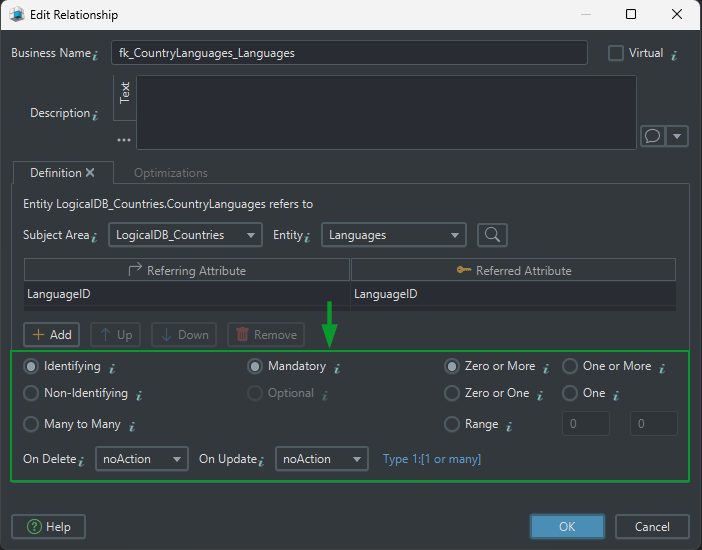
Identifying and non-identifying relations
In an identifying relation the parent's key becomes part of the child's identifier, so the child cannot exist on its own. A phone prefix means nothing without its country, which is why CountryID sits inside the key of PhonePrefixes.
In a non-identifying relation the child references the parent and keeps its own identity: a City keeps CityID and merely points at a Country. Choose identifying only where the child genuinely has no meaning alone, because the parent key then propagates into the key of every entity below it.
Cardinality
| Cardinality | What it says | How it is implemented |
|---|---|---|
| 1:1 | one record matches one record | usually a sign the two entities should be one |
| 1:n | one parent, many children | a foreign key on the child |
| m:n | many on both sides | a junction entity, which often carries attributes of its own |
Mandatory and optional relations
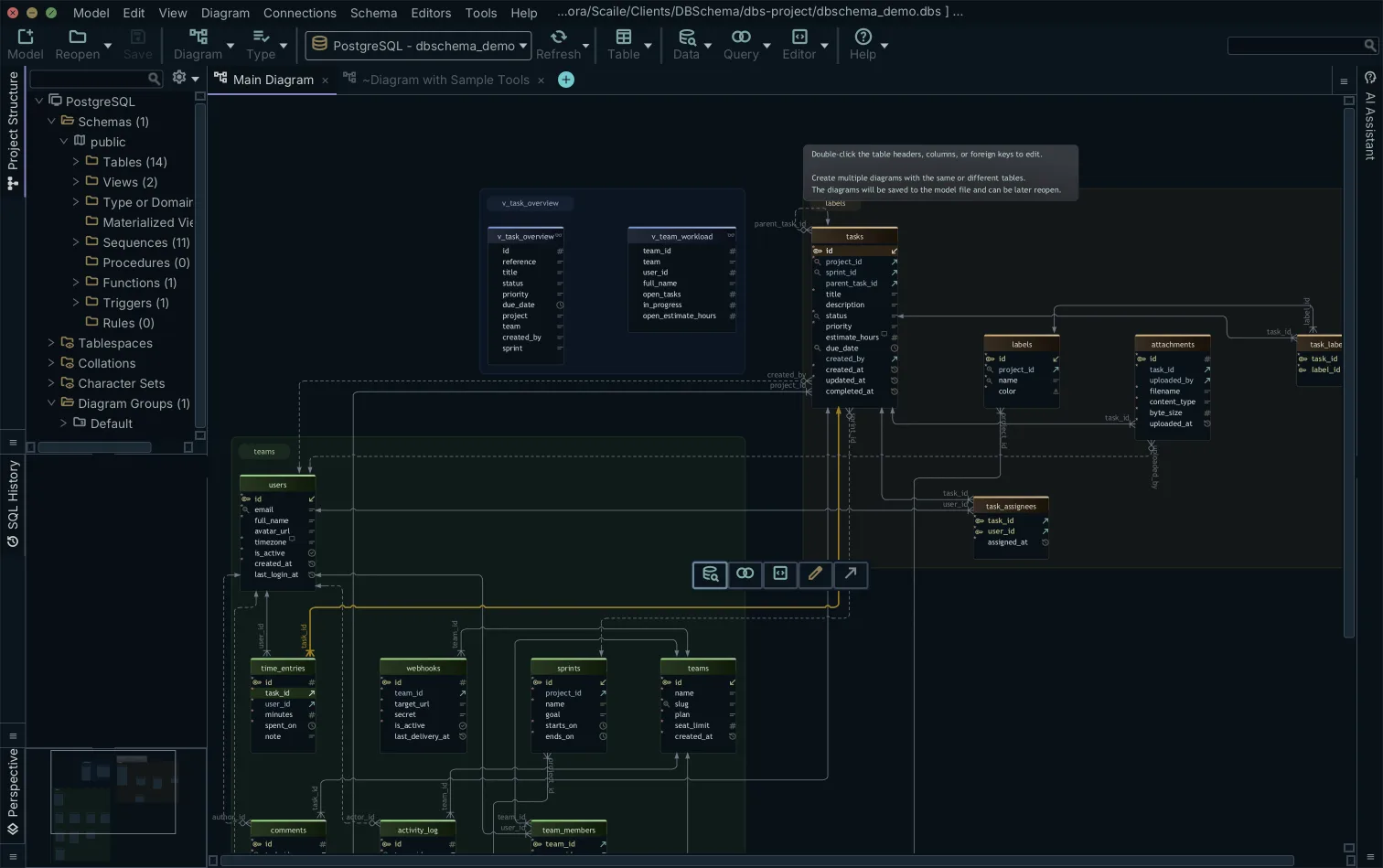
Mandatory means the child must reference a parent, and the column becomes NOT NULL. Optional means it may exist without one, and every query that joins it needs an outer join. Decide this per relation: a model in which optional is the default is a model in which no join result can be relied on.
Virtual foreign keys when the database enforces nothing
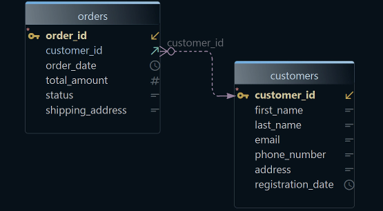
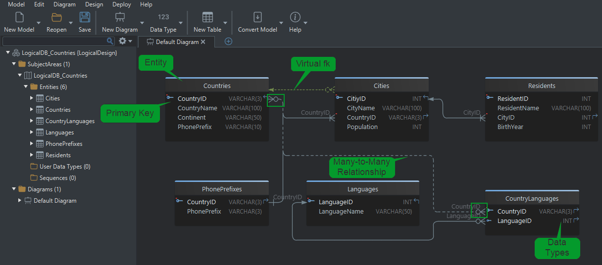
Some relations are real in the data and absent from the database: views, imported datasets, tables whose constraints were never created. In DbSchema you draw one by dragging a column onto the related column in the diagram and choosing a virtual foreign key when it asks. The line is saved in the model file, and nothing is sent to the database, so the relation is documented without a constraint being created. The Query Builder and the Relational Data Editor, both in the Pro edition, then join across that line as if the engine had declared it, which is what gives imported and legacy tables a readable join path.
Normalization in one pass
Normalization belongs to logical design because a model is cheap to change and a deployed schema holding data is not. Three forms cover almost every practical case, and one record shows all three.
1NF puts one value in each attribute
An order arrives as a single record, and one of its fields holds a list rather than a value:
OrderID       101
CustomerName  Alice Smith
PhoneNumber   555-1234
Products      Shoes, T-shirt
One value per attribute splits that field across rows:
| OrderID | CustomerName | Product | PhoneNumber |
|---|---|---|---|
| 101 | Alice Smith | Shoes | 555-1234 |
| 101 | Alice Smith | T-shirt | 555-1234 |
Every attribute can now be filtered, validated and indexed on its own, which no value inside a comma-separated list can be.
2NF removes partial dependencies
The key of the split table is OrderID and Product together, while the customer's name and phone number depend on OrderID alone. Putting the key columns first makes that partial dependency easy to see:
| OrderID | Product | CustomerName | PhoneNumber |
|---|---|---|---|
| 101 | Shoes | Alice Smith | 555-1234 |
| 101 | T-shirt | Alice Smith | 555-1234 |
Splitting the order-level facts from the line-level ones puts each at its own grain. Orders keeps one row per order:
| OrderID | CustomerName | PhoneNumber |
|---|---|---|
| 101 | Alice Smith | 555-1234 |
OrderDetails keeps one row per product on that order:
| OrderID | Product |
|---|---|
| 101 | Shoes |
| 101 | T-shirt |
3NF removes transitive dependencies
Orders now carries a customer identifier, and the name and the phone number depend on that identifier rather than on the order:
| OrderID | CustomerID | CustomerName | PhoneNumber |
|---|---|---|---|
| 101 | C001 | Alice Smith | 555-1234 |
Moving the customer's details into their own entity means a phone number is updated in one row. Orders keeps the identifier and nothing else about the customer:
| OrderID | CustomerID |
|---|---|
| 101 | C001 |
Customers keeps the details, once per customer:
| CustomerID | CustomerName | PhoneNumber |
|---|---|---|
| C001 | Alice Smith | 555-1234 |
Each form removes a different defect:
| Normal form | What it removes | The symptom it cures |
|---|---|---|
| 1NF | repeating groups and non-atomic values | a value inside a list cannot be queried or constrained |
| 2NF | partial dependencies on a composite key | the same fact is repeated on every line item |
| 3NF | transitive dependencies between non-key attributes | one business change means many row updates |
Stop at 3NF unless a measured query says otherwise. Going further splits tables that nothing complains about, and every split adds a join to the queries that were already correct. For the cases beyond the third form, see Database Normalization.
Naming and type conversion
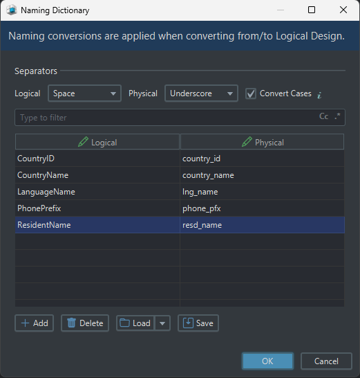
A logical model uses business names and abstract types, so two mappings stand between it and something an engine accepts. The naming dictionary decides how a logical name is written physically, turning First Name into first_name or FIRST_NAME by a rule rather than by hand; open it from the DbSchema "Convert Model" menu. The translation happens during the conversion, so the logical model keeps the business names a reviewer reads, and the physical model gets the identifiers the engine sees.
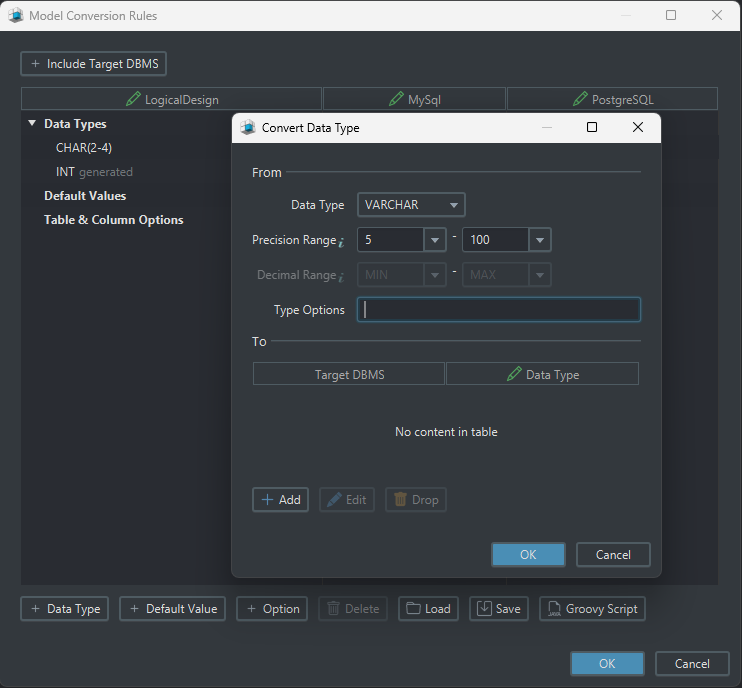
The conversion dictionary maps each logical type to a physical one per target database: the logical type Text converts to VARCHAR(255) for MySQL and NVARCHAR(255) for SQL Server, and you can edit the mapping for any database to match your own conventions. Keeping both as rules is what lets one logical model target several engines without the models drifting apart. Doing it by hand instead means a rename in the logical model is a rename you then repeat once per engine, and the second engine is where the two schemas quietly stop matching.
From logical model to physical schema
With the decisions above made, the conversion is mechanical.
| Logical | Physical |
|---|---|
| entity | table |
| attribute | column |
| identifier | primary key |
| relation | foreign key |
| identifying relation | parent key inside the child's primary key |
| mandatory relation | NOT NULL on the foreign key column |
| cardinality m:n | junction table |
You run the conversion in DbSchema:
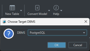
- Choose "Convert Model → Generate Physical Design".
- Pick the target database.
- Review the generated tables, columns and constraints.
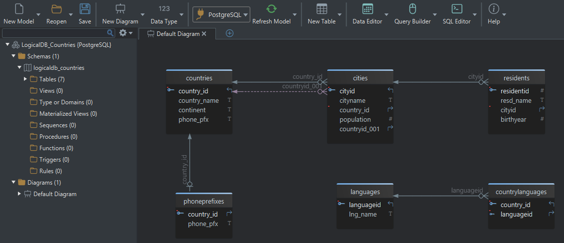
DbSchema applies the two dictionaries and produces an editable physical model. The conversion writes that model into the same .dbs file and sends nothing to a database. The schema reaches the database only when you connect and apply it.
What the conversion cannot decide for you is indexes, storage and collation. Those are physical choices, and they are made against the queries the application actually runs rather than inherited from the logical model.
Entities, identifiers, cardinality, optionality and normal form are the five decisions that cost the most to change later, and every one of them is made before an engine is chosen. Download DbSchema at https://dbschema.com/download.html, choose Design from Scratch on the welcome screen and then Logical Design, and right-click the canvas to draw the first entity. Database-independent logical design is in the Architect edition, which also carries everything the Pro and Community editions have. The diagram side of the work is described in the database diagrams tool.
FAQ
What is the difference between logical and physical database design?
Logical design names entities, attributes, identifiers and relations, and stays engine-neutral. Physical design turns each of those into a table, a typed column, a primary key or a foreign key constraint for one database, and adds the indexes and storage settings that only make sense once the engine is known.
Can one logical model target more than one database?
One model can target several, because the naming and conversion dictionaries hold the rules rather than the model holding engine syntax. DbSchema retargets an existing model from "Model → Model Properties", showing a preview of how every data type converts before you confirm. Triggers, functions and stored procedures are written per engine, since their languages differ.
Do I still need logical design if I already know SQL?
SQL implements a structure, and logical design is where you decide whether that structure is the right one. Typing DDL quickly does not answer whether a phone prefix is an attribute or an entity.
Which DbSchema edition includes logical design?
Logical and conceptual design are in the Architect edition. Connecting, reverse-engineering, interactive diagrams and the SQL editor are in the free Community edition, and saving the model to a file, schema synchronization, model validation and the visual query builder are in Pro.
Model the structure before you pick an engine
DbSchema keeps entities, identifiers and relationships in one model file, validates it, and converts it into the physical schema for your target database.