Logical Database Design – Entities, Keys, Normalization, and Physical Mapping | DbSchema
Logical database design is the stage where a database becomes clear enough to build. It sits between high-level business ideas and physical SQL implementation. Here you decide entities, attributes, identifiers, relationships, and normalization rules before you worry about engine-specific syntax.
For modern teams, this step matters more than ever: the schema must be readable by developers, analysts, and product stakeholders, then converted cleanly into MySQL, PostgreSQL, SQL Server, Oracle, or another engine. DbSchema is especially useful because the same model can move from logical design to diagram review, validation, and schema documentation.
Table of Contents
- Logical vs conceptual vs physical design
- How to start a logical design in DbSchema
- Entity-to-table mapping
- Defining identifiers and relationships
- Normalization with 1NF, 2NF, and 3NF
- Naming and conversion dictionaries
- Validate and collaborate on the model
- Deploy into physical design
- FAQ
- Conclusion
Logical vs conceptual vs physical design
One reason logical design is often misunderstood is that teams mix it with conceptual or physical design. They are related, but not identical.
| Design level | Focus | Typical output | Best use |
|---|---|---|---|
| Conceptual | business concepts | broad entities and relationships | stakeholder discussions |
| Logical | data structure and rules | entities, attributes, keys, cardinality, normalization | design review and planning |
| Physical | implementation details | tables, data types, indexes, constraints, engine-specific SQL | deployment and optimization |
Logical design is where you answer questions such as:
- what entities does the domain need?
- which attribute identifies each entity?
- which relationships are mandatory?
- where should many-to-many relationships become junction tables?
- how far should the model be normalized before implementation?
If you need a practical design-first walkthrough, pair this article with How to Design a Relational Database Schema and Entity Relationship Diagram.
How to start a logical design in DbSchema
You can download DbSchema and create a logical model before any database exists.
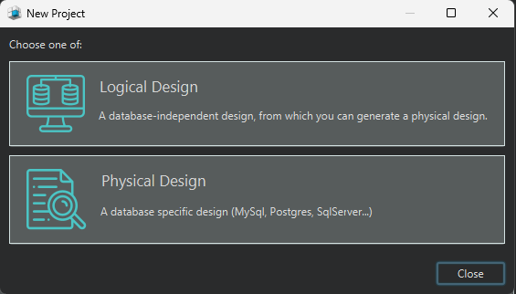
- Open DbSchema.
- In the Welcome Pane, choose Design from Scratch.
- Select Logical Design.
- Add entities, attributes, and relationships to the diagram.
This workflow is useful when the business model is still evolving because you can review the structure first, then decide later whether the target engine is MySQL, PostgreSQL, SQL Server, or something else.
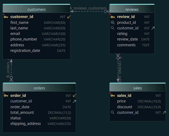
Entity-to-table mapping
Logical design usually starts by translating real-world objects into entities.
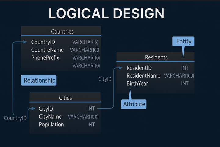
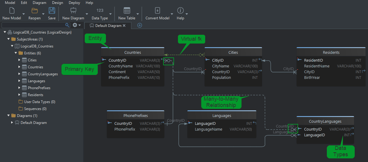
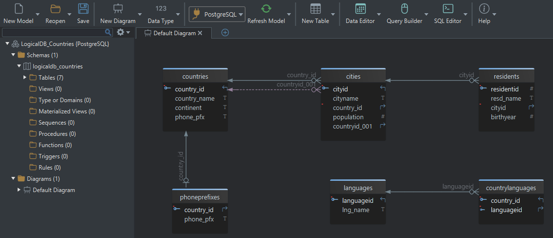
Example: country and population model
Suppose we model geographic data:
Countries (CountryID, Name, Continent, PhonePrefix)Cities (CityID, Name, CountryID, Population)Residents (ResidentID, Name, CityID, BirthYear)
In logical design:
- each entity becomes a future table
- each attribute becomes a future column
- each relationship becomes a future foreign key
| Business idea | Logical design result | Physical result later |
|---|---|---|
| country exists | Countries entity | countries table |
| city belongs to country | relation from Cities to Countries | foreign key |
| resident belongs to city | relation from Residents to Cities | foreign key |
The main benefit of this stage is clarity. It is much easier to spot duplication, missing lookup tables, or bad naming in a diagram than after hundreds of lines of DDL already exist.
Defining identifiers and relationships
Primary key (logical identifier)
Every entity needs an identifier that uniquely distinguishes one record from another.
Examples
CountryIDidentifies each countryCityIDidentifies each cityResidentIDidentifies each resident
When the model becomes physical, these identifiers become primary keys.
Logical relationships
Relationships describe how entities connect. In the logical model, they are conceptual. In the physical model, they become enforced foreign keys.
Cities.CountryID → Countries.CountryID
Residents.CityID → Cities.CityID
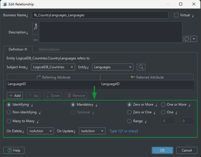
Relationship decisions you should make early
| Question | Why it matters | Example |
|---|---|---|
| Is the relationship identifying? | determines whether the parent key is part of the child key | PhonePrefixes(CountryID, PhonePrefix) |
| Is it mandatory or optional? | affects nullability and business rules | each City must belong to a Country |
| What is the cardinality? | clarifies one-to-one, one-to-many, or many-to-many | one Country has many Cities |
| What happens on delete or update? | affects future physical constraints | ON DELETE CASCADE vs NO ACTION |
Identifying vs non-identifying
- Identifying relationship: the parent key becomes part of the child identifier. The child depends on the parent for identity.
- Non-identifying relationship: the child references the parent, but the parent key is not part of the child identifier.
One-to-many and many-to-many
- One-to-many: one country can have many cities.
- Many-to-many: many countries can speak many languages, so you need a junction entity such as
CountryLanguages.
Mandatory vs optional
- Mandatory: the child must reference a parent.
- Optional: the child may exist without the parent reference.
Cardinality
1:1— one record matches one record1:n— one parent matches many childrenm:n— many records on both sides, implemented through a junction entity
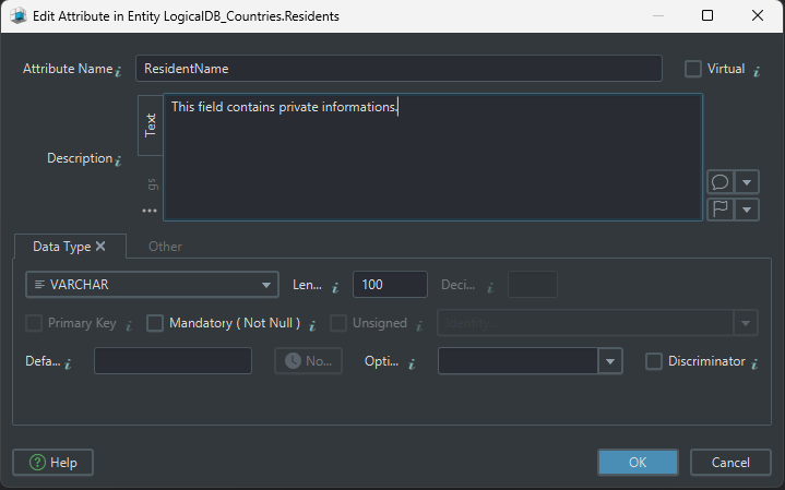
Virtual foreign keys in DbSchema
DbSchema also supports virtual foreign keys. These are relationships defined in the model even when the database itself does not enforce them. They are useful for:
- documenting views or imported data
- connecting legacy tables that lack real constraints
- helping the Query Builder and Relational Data Editor understand how tables relate
Normalization with 1NF, 2NF, and 3NF
Normalization organizes the model so data stays consistent and duplication stays low. Logical design is the perfect place to do this because it is easier to change the model before the physical schema is deployed.
We will use a simple online-store example.
First Normal Form (1NF)
Goal: every attribute stores one atomic value.
Not in 1NF
| OrderID | CustomerName | Products | PhoneNumbers |
|---|---|---|---|
| 101 | Alice Smith | Shoes, T-shirt | 555-1234, 555-5678 |
| 102 | Bob Lee | Laptop | 555-1111 |
Problems:
Productsstores a list instead of one valuePhoneNumbersstores repeated values inside one cell
In 1NF
| OrderID | CustomerName | Product | PhoneNumber |
|---|---|---|---|
| 101 | Alice Smith | Shoes | 555-1234 |
| 101 | Alice Smith | T-shirt | 555-5678 |
| 102 | Bob Lee | Laptop | 555-1111 |
What changed in the model? We removed repeating groups so each attribute can be filtered, validated, and indexed independently.
Second Normal Form (2NF)
Goal: remove partial dependencies when a composite key exists.
Assume (OrderID, Product) is the key.
Not in 2NF
| OrderID | Product | CustomerName | PhoneNumber |
|---|---|---|---|
| 101 | Shoes | Alice Smith | 555-1234 |
| 101 | T-shirt | Alice Smith | 555-1234 |
CustomerName and PhoneNumber depend only on OrderID, not on the entire key.
In 2NF
Orders
| OrderID | CustomerName | PhoneNumber |
|---|---|---|
| 101 | Alice Smith | 555-1234 |
OrderDetails
| OrderID | Product |
|---|---|
| 101 | Shoes |
| 101 | T-shirt |
What changed in the model? We separated order-level data from line-item data so each non-key attribute depends on the full key of its entity.
Third Normal Form (3NF)
Goal: remove transitive dependencies.
Not in 3NF
| OrderID | CustomerID | CustomerName | PhoneNumber |
|---|---|---|---|
| 101 | C001 | Alice Smith | 555-1234 |
CustomerName and PhoneNumber depend on CustomerID, not directly on OrderID.
In 3NF
Orders
| OrderID | CustomerID |
|---|---|
| 101 | C001 |
Customers
| CustomerID | CustomerName | PhoneNumber |
|---|---|---|
| C001 | Alice Smith | 555-1234 |
What changed in the model? We moved customer details into their own entity, which means customer data is updated in one place instead of many.
Normal forms summary
| Normal form | What it fixes | Why it helps |
|---|---|---|
| 1NF | repeating groups and non-atomic values | makes attributes searchable and consistent |
| 2NF | partial dependencies on composite keys | keeps entities focused on one grain |
| 3NF | transitive dependencies | prevents duplicate maintenance work |
If you want the full design workflow around normalization, the related guide How to Design a Relational Database Schema expands the same ideas with a complete example.
Naming and conversion dictionaries
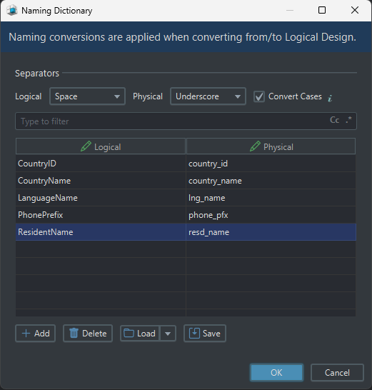
Naming dictionary
The naming dictionary controls how logical names become physical names.
Examples:
Customer Name→customer_namePhone Prefix→phone_prefixCountryID→country_id
This helps keep the generated schema consistent across the whole project.
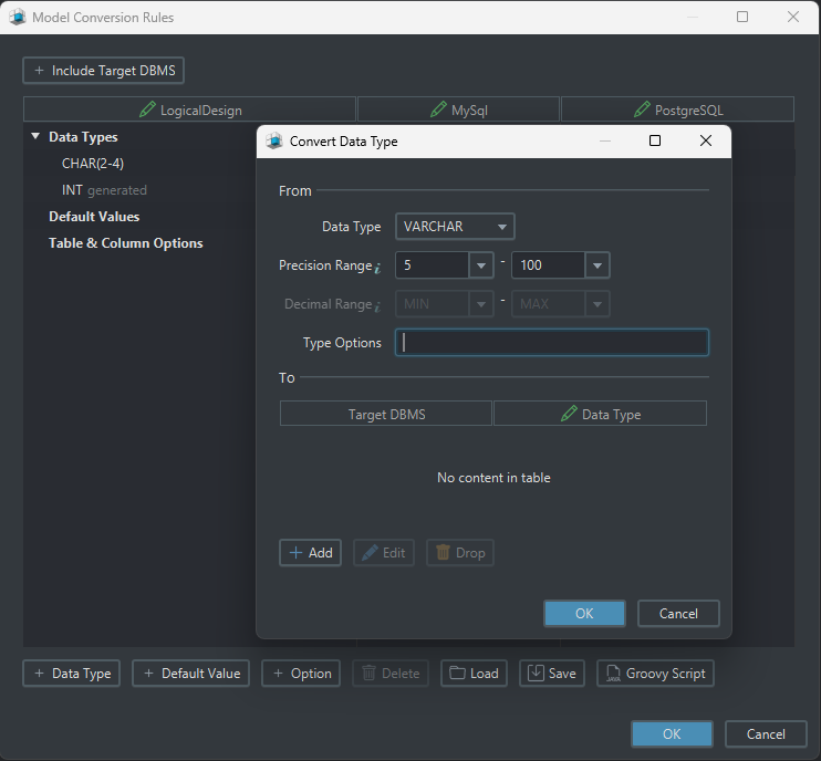
Conversion dictionary
The conversion dictionary maps logical data types to physical ones for each target database.
Examples:
- logical
Text→ MySQLVARCHAR(255) - logical
Text→ SQL ServerNVARCHAR(255) - logical
Number→ PostgreSQLINTEGER
This is one reason DbSchema works well in multi-database teams: the logical model stays stable while the physical implementation can change per engine.
Validate and collaborate on the model
Once the model looks right, review it as if another team will inherit it tomorrow.
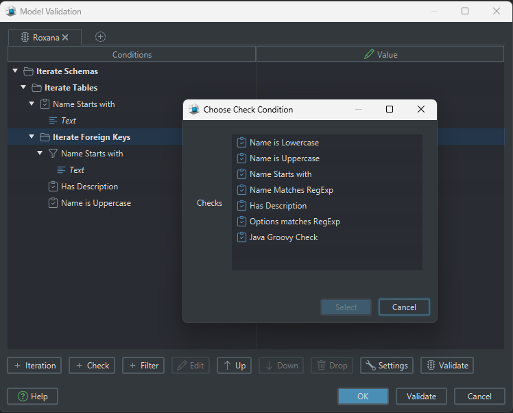
Schema and table validation
DbSchema can check for:
- missing primary keys
- problematic relationships
- redundant structures
- cyclic dependencies
- inconsistent naming
Comments and tags
Comments and tags make the model easier to reuse in documentation and team reviews.
- annotate tables and columns with purpose
- mark important entities with tags
- explain abbreviations or business rules
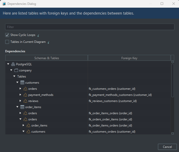
Find cyclic dependencies
Circular dependencies often signal a design problem. DbSchema can highlight them visually, which is much faster than discovering them only during migration or test setup.
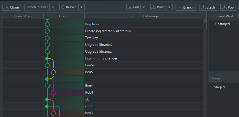
Git integration for teamwork
Logical models are not just for one person on one laptop. DbSchema can store the design in a model file and help teams review it with Git workflows before changes reach production.
Deploy into physical design
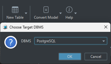
When the logical model is ready:
- click Convert Model
- choose Generate Physical Model
- select the target DBMS
- review the generated tables, columns, and constraints
DbSchema then maps:
- entities → tables
- attributes → columns
- identifiers → primary keys
- relations → foreign keys
From there you can continue with connect to database, schema synchronization, and published documentation.
FAQ
What is logical database design?
Logical database design defines entities, attributes, identifiers, relationships, and normalization rules without locking the schema to one database engine.
What is the difference between logical and physical database design?
Logical design is database-neutral and focuses on structure. Physical design adds data types, indexes, constraints, and engine-specific implementation details.
Why is normalization part of logical design?
Because it is easier to remove duplication and clarify relationships before the schema becomes a deployed database with live data.
Do I need logical design if I already know SQL?
Yes. SQL helps you implement the schema, but logical design helps you decide whether the structure is correct before implementation.
Can DbSchema create a logical model without a live database?
Yes. That is one of its biggest advantages: you can design offline, review the model, then generate or synchronize the physical schema later.
What is the best tool for logical database design?
If you want design-first modeling, multiple diagrams, validation, Git workflow, and later physical conversion in one product, DbSchema is a strong choice.
Conclusion
Logical database design is the stage where database quality is decided. If the entities, identifiers, cardinality, and normalization are right here, the physical schema becomes much easier to implement and maintain.
DbSchema is especially effective because it keeps the logical model useful after the workshop is over: the same design can be validated, versioned, converted, synchronized, and documented.