Create a Logical Database Design with DbSchema
A logical design in DbSchema is an independent model that defines entities (tables), their attributes (columns), and relationships - without being tied to any specific database system.
It helps visualize how data is structured and connected before implementation. Once finalized, the design can be converted into a physical model tailored for databases like MySQL, PostgreSQL, SQL Server, and 80+ databases.
I. How to Start a Logical Design in DbSchema
You can download DbSchema and try it for yourself.
Once installed:
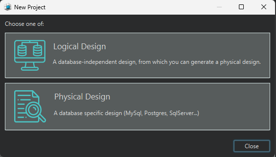
- Open DbSchema.
- From the Welcome Pane, select Design from Scratch (available in the PRO edition).
- Choose Logical Design to start creating your schema using entities, attributes, and relationships — independent of any database engine.
This lets you build and validate your model visually before committing to a specific database system.
Logical Design in DbSchema
- Entity-to-Table Mapping
- Defining Identifiers and Relationships
- Normalization
- Naming Dictionary & Conversion Dictionary
- Schema & Table Validation
- Comments and Tags in DbSchema
- Find Cyclic Dependencies
- Git Integration for Team Collaboration
- Deploy into Physical Design
1. Entity-to-Table Mapping
Entity mapping is the foundation of logical design. Each entity in the conceptual design becomes a table in the logical model.
- Attributes (Fields) become table columns.
- Relationships represent how entities are connected and will later be implemented as foreign keys.
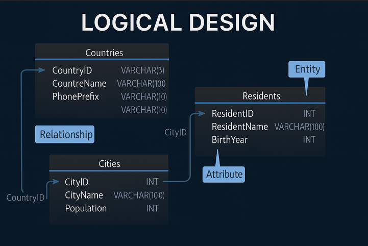
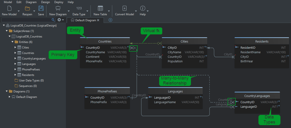
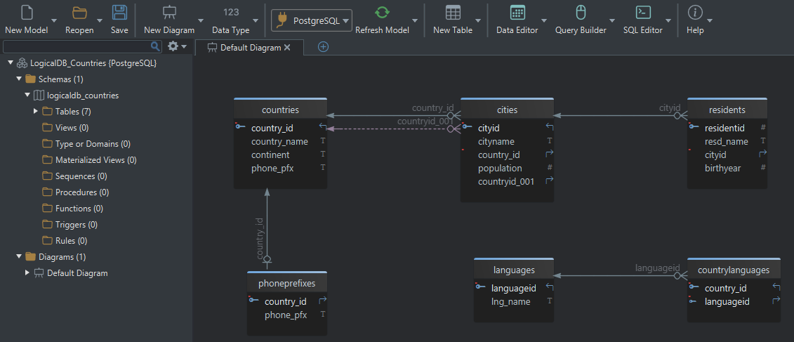
Example: Country & Population Model
For a global database, we might define these entities:
Countries (CountryID, Name, Continent, PhonePrefix)Cities (CityID, Name, CountryID, Population)Residents (ResidentID, Name, CityID, BirthYear)
Each entity will become a table, and relationships between them will be implemented through foreign keys in the physical model.
2. Defining Identifiers and Relationships
Primary Key (Logical ID)
In logical design, each entity needs an identifier - an attribute (or combination) that uniquely distinguishes each record. This becomes the Primary Key in the physical model.
Examples:
CountryIDuniquely identifies each country.CityIDidentifies each city.
Logical Relationships
Entities often reference other entities. In logical design, these are conceptual links. In physical design, they become foreign keys.
Example:
Cities.CountryIDconnects cities to countries.
Cities.CountryID → Countries.CountryID (Logical Relationship)
Types of Relationships
In the logical design phase, we define how entities are related to one another - without worrying yet about how these will be implemented in a database. These relationships describe how data connects conceptually.
Later, in the physical design, these logical relationships are implemented as foreign keys, which enforce rules in the database about how tables relate.
DbSchema helps define and manage both logical and physical relationships, supporting many types of foreign keys to reflect different scenarios.
Identifying vs. Non-Identifying Relationships
These define how tightly connected a child entity is to its parent.
-
Identifying Relationship:
The relationship is essential to the child’s identity. The parent entity's key becomes part of the child entity's key.This means the child cannot exist without the parent, and its identity depends on the parent.
Example:
Let’s say we have aCountriesentity and aPhonePrefixesentity.Countriesis the parent (identified byCountryID)PhonePrefixesis the child
In the logical model,
PhonePrefixesuses bothCountryIDandPhonePrefixto form its unique identifier:PhonePrefixes(CountryID, PhonePrefix) -
Non-Identifying Relationship:
The relationship is optional for identification. The parent’s key is referenced, but it is not part of the child’s identifier.The child can exist independently of the parent.
Example:
Suppose we have aCitiesentity and aResidentsentity:Citiesis the parent (withCityIDas its identifier)Residentsis the child
In this case,
Residents.CityIDreferencesCities.CityID, but it is not part of the primary key ofResidents.
This means a resident can be related to a city, but their identity doesn’t depend on it.
One-to-Many and Many-to-Many Relationships
-
One-to-Many:
A single record in one entity is related to multiple records in another entity.Example: One country can have many cities, but each city belongs to only one country.
Countriesis the parent (withCountryID)Citiesis the child (withCountryIDas a foreign key)
-
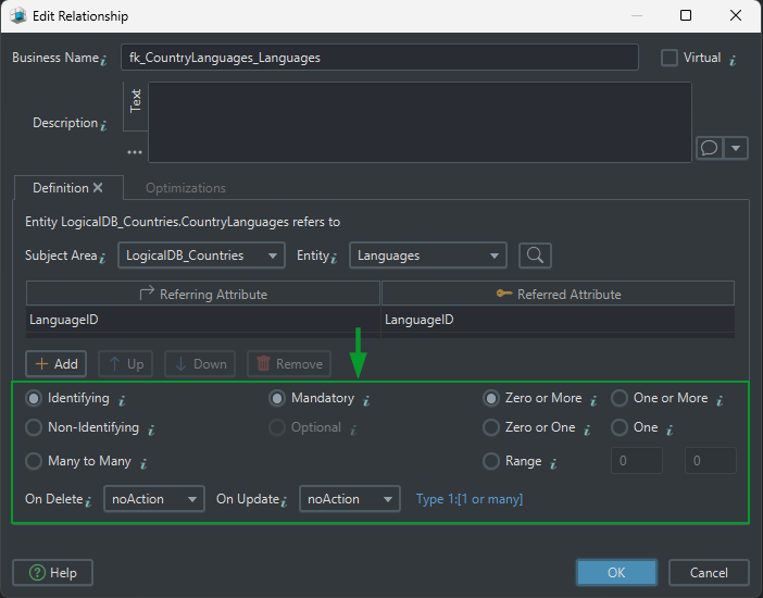
Many-to-Many:
Records in both entities can be related to multiple records in the other.
This requires a junction entity (also called a bridge or associative table) to connect them.Example: A
CountryLanguagesentity (withCountryIDandLanguageID) shows which languages are spoken in which countries.CountriesandLanguagesare related through the junction entityCountryLanguages
Mandatory vs. Optional Relationships
These relationships define whether a link between two entities is required.
-
Mandatory Relationship:
The child entity must be linked to a parent entity.Example:
Cities.CountryIDis required - every city must belong to a country.
Example:Residents.CityIDis required - every resident must belong to a city. -
Optional Relationship:
The child entity may or may not be linked to a parent entity.Note: In the current database design, all relationships are mandatory. Optional relationships can be introduced if future data requirements allow for missing links (e.g., not all residents are assigned to a location).
Cardinality (0.., 1.., 0..1, etc.)
Cardinality defines how many records in one entity can relate to records in another:
-
Zero or More (
0..*):
A country may have no residents. -
One or More (
1..*):
Each city must have at least one resident. -
Zero or One (
0..1):
A city may or may not have any residents - for example, newly built or uninhabited cities. -
Exactly One (
1):
Each phone prefix must belong to exactly one country. -
Range (
X..Y):
Sets a minimum and maximum number of related records.Example: A team must have between 2 and 5 members.
On Delete / Update Actions
When a parent record is deleted or updated, foreign keys determine what happens to related data:
-
ON DELETE CASCADE:
Automatically deletes related records in the child table. -
ON DELETE NO ACTION:
Prevents deletion if related child records exist. -
ON DELETE SET NULL:
Sets the foreign key in the child table toNULL, effectively removing the link.
These behaviors are part of the physical design and are fully supported by DbSchema.
Virtual Foreign Keys in DbSchema
DbSchema allows defining virtual foreign keys - logical relationships that do not exist in the actual database schema. These are useful when:
- Working with views or external data sources
- Modeling relationships not enforced by the database
- It can be used in Query Builder or Data Editor to simulate a real foreign key.
These virtual keys are especially valuable for documenting or exploring data without altering the actual database structure.
3. Normalization
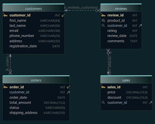
Normalization means organizing your data in a way that removes duplication and keeps it clean. It helps break down big, messy tables into smaller ones, where each table focuses on just one thing.
This makes the database easier to update, and helps avoid mistakes like storing the same info in multiple places.
We’ll use a real-world example based on customer orders in an online store.
First Normal Form (1NF)
Goal: Make sure each column contains a single, indivisible value : no lists or grouped data.
The problem:
Productsholds multiple items in one field (e.g., “Shoes, T-shirt”).PhoneNumbersstores more than one value (e.g., “555-1234, 555-5678”).- This breaks atomicity and makes filtering or updating individual values difficult.
✖️ Not in 1NF:
| OrderID 🗝️ | CustomerName | Products | PhoneNumbers |
|---|---|---|---|
| 101 | Alice Smith | Shoes, T-shirt | 555-1234, 555-5678 |
| 102 | Bob Lee | Laptop | 555-1111 |
The solution: Split multi-value fields into separate rows, so each cell holds only one value.
✔️ 1NF (Atomic values only):
| OrderID 🗝️ | CustomerName | Product | PhoneNumber |
|---|---|---|---|
| 101 | Alice Smith | Shoes | 555-1234 |
| 101 | Alice Smith | T-shirt | 555-5678 |
| 102 | Bob Lee | Laptop | 555-1111 |
1NF is the foundation for clean, searchable, and maintainable data.
Second Normal Form (2NF)
Goal: Eliminate partial dependencies : every non-key column must depend on the entire primary key (not just part of it).
The problem:
Assume OrderID + Product is the composite primary key.
But here, CustomerName and PhoneNumber depend only on OrderID.
✖️ Not in 2NF:
| OrderID 🗝️ | Product 🗝️ | CustomerName | PhoneNumber |
|---|---|---|---|
| 101 | Shoes | Alice Smith | 555-1234 |
| 101 | T-shirt | Alice Smith | 555-1234 |
- This causes repetition of customer info and violates 2NF.
The solution: Split the table into two:
- One table for the order (customer-related data)
- One for the order details (products)
✔️ 2NF (After splitting):
Orders Table: | OrderID 🗝️ | CustomerName | PhoneNumber | |------------|--------------|-------------| | 101 | Alice Smith | 555-1234 |
OrderDetails Table: | OrderID 🗝️ | Product 🗝️ | |------------|------------| | 101 | Shoes | | 101 | T-shirt |
Now:
CustomerNameandPhoneNumberdepend only onOrderIDin theOrderstableProductdepends on the full key inOrderDetails
✔ This removes partial dependencies and prepares your design for 3NF.
Third Normal Form (3NF)
Goal: Eliminate transitive dependencies : non-key columns should depend directly on the primary key, not on other non-key columns.
The problem:
In this table, OrderID is the primary key, but CustomerName and PhoneNumber depend on CustomerID, which is not the key.
This is a transitive dependency - and it breaks 3NF.
✖️ Not in 3NF:
| OrderID 🗝️ | CustomerID | CustomerName | PhoneNumber |
|---|---|---|---|
| 101 | C001 | Alice Smith | 555-1234 |
- Changing a customer's name or phone would require editing every order they’re in.
The solution:
Split customer data into its own table and reference it by CustomerID.
✔️ 3NF (After normalization):
Orders Table: | OrderID 🗝️ | CustomerID 🔑 | |------------|---------------| | 101 | C001 |
Customers Table: | CustomerID 🗝️ | CustomerName | PhoneNumber | |----------------|---------------|-------------| | C001 | Alice Smith | 555-1234 |
Now:
- All non-key columns depend only on the primary key of their respective tables.
- No transitive dependency exists between non-key attributes.
✔ 3NF keeps your data clean, avoids duplication, and simplifies updates.
Normal Forms Summary
| Normal Form | What It Fixes | How It Helps |
|---|---|---|
| 1NF | Repeating groups & non-atomic values | Ensures each field holds one value |
| 2NF | Partial dependencies on composite keys | Separates data by full key dependency |
| 3NF | Transitive dependencies between columns | Removes indirect links between values |
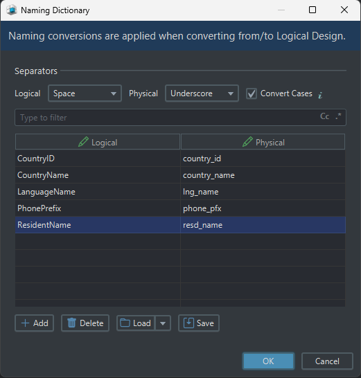
4. Naming Dictionary & Conversion Dictionary
Naming Dictionary
Helps you control how names are formatted when switching between logical and physical database designs.
In the logical design, names are usually written in a human-readable style like CountryID or PhonePrefix. But when generating the physical database model, those names can be automatically converted into formats better suited for the target database system.
Eample:
country_idorphone_pfx, using underscores and lowercase letters.
This naming system ensures:
- Consistency across the entire model
- Better readability in SQL scripts
- Compatibility with different naming standards (e.g., snake_case for PostgreSQL)
Conversion Dictionary
Adds another layer of clarity. It defines:
- What each table represents in the real world
- What each column stores (including data types and purpose)
- How tables are related to each other through foreign keys
Together, the naming and conversion dictionaries support clean design, simplify implementation, and improve team collaboration across development, testing, and deployment.
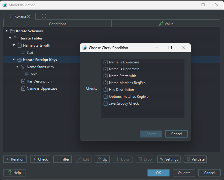
5. Schema & Table Validation
DbSchema provides a Validation tool to check schema consistency:
- Detects missing primary keys and orphaned foreign keys.
- Verifies naming conventions and redundant data.
- Ensures relationships follow best practices (e.g., cyclic dependencies, many-to-many with junction tables).
- Suggests virtual foreign keys where needed.
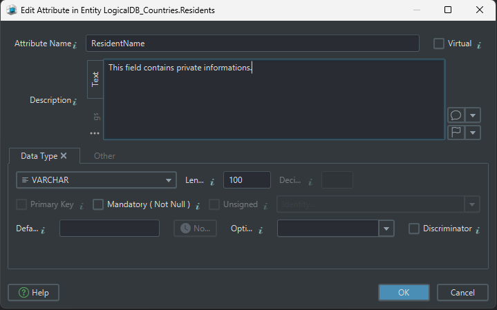
6. Comments and Tags in DbSchema
In DbSchema, when creating a logical design, you can easily add comments and tags to elements like tables, columns, and foreign keys:
- Add clear annotations to explain the purpose of a design element.
- Use tags to categorize or highlight important elements for better organization.
- Include detailed comments that can be useful for collaboration and future reference.
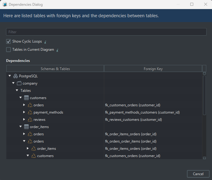
7. Find Cyclic Dependencies
A cyclic dependency is when columns or tables depend on each other in a loop. This tool highlights any circular relationships that could cause issues in your data model.
In DbSchema, you can easily check for loops in your design using:
Diagram → Find Cyclic Dependencies
In our current design, there are no cyclic dependencies - and that’s a good thing.
Example of a problem (not in your design):
If the number of residents (Residents) was used to calculate the city’s population, and the city’s population was also stored separately in theCitiestable, the two would depend on each other in a loop. That would be a cyclic dependency - and it’s best to avoid that.
In our schema, everything flows one direction:
Countries → Cities → Residents, which keeps the design clean and reliable.
But here is an example with a lot of cyclic dependencies from another PostgreSQL database:
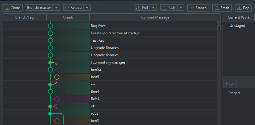
8. Git Integration for Team Collaboration
DbSchema's Git integration allows you to save your logical design as a model file and share it with your team for collaborative work. With Git, you can:
- Track changes made to the database design, ensuring that everyone is on the same page.
- Collaborate efficiently, as team members can clone the repository, modify the model, and push or pull changes.
- Work in parallel and merge updates, avoiding conflicts and maintaining an up-to-date version of the schema.
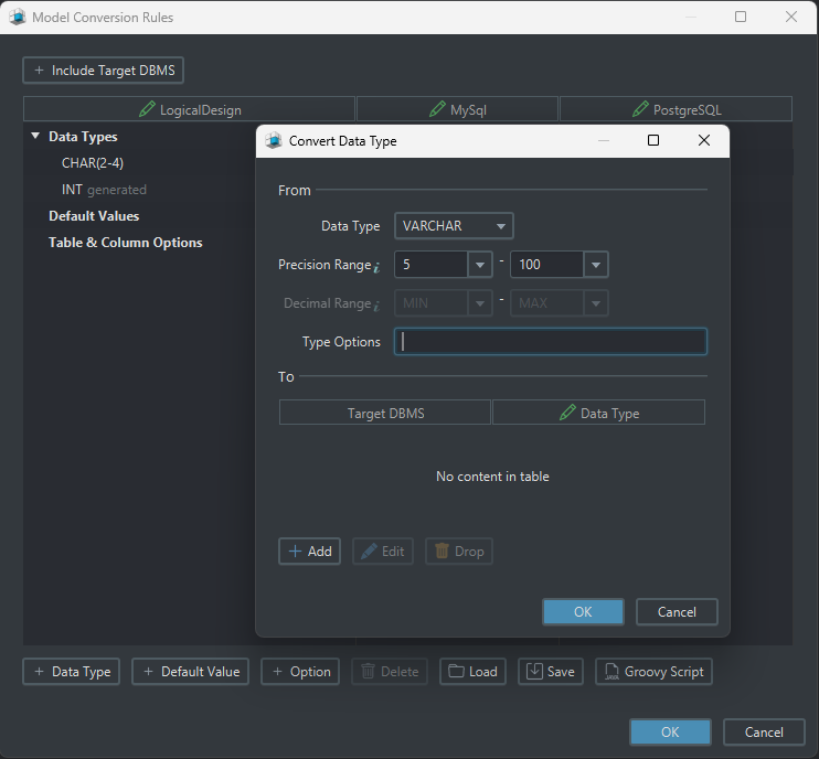
II. Deploy to Physical Design
Once your logical model is complete, you can easily convert it into a physical model adapted to your preferred database system.
To do this in DbSchema:
- Click on Convert Model from the icon bar.
- Choose Generate Physical Model.
- Select your target DBMS.
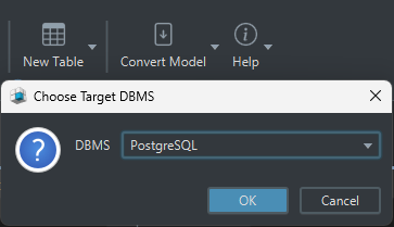
In this example, I've chosen PostgreSQL, but you can select any supported database system that suits your project requirements.
DbSchema will automatically map your logical entities, attributes, and relationships into physical tables, columns, and constraints specific to the chosen database engine.
Conclusion
Logical design ensures database integrity and scalability. By following these steps and validating your schema, you create a solid foundation before moving to physical modeling.
You can learn more about the features DbSchema offers for your database in this article.